In accordance with ISO 80000-2, the following font conventions are employed:
Scalars and components for vectors or tensors are represented by lightface italic type ().
Vectors are represented by boldface italic type ().
Second-order tensors are represented by boldface sans-serif type ().
Operators & Constants: Roman (upright) type is used for fixed mathematical constants (e.g., Pi , the imaginary unit ) and differential operators (e.g., the differential in ).
Calculus Notation: For integrals, a thin space (\,) is used to separate the integrand from the differential operator, e.g., .
Minkowski Metric: The Minkowski metric tensor is defined using the mostly-plus signature convention:
Consequently, the invariant spacetime interval is given by .
Lorentz transformation
For -axis boost (where moves with velocity relative to ), the transformation matrix is:
1 Electrostatic Field
1.1 Multipole expansion
Consider electrostatic potential expansion at an external observation point , with localized charge source confined within a volume , and , then
Where is total charge, is electric dipole moment, is electric quadrupole moment.
Electrostatic intensity expansion
1.2 Small charged body in electric field
Assuming the charge of charged bodies is so small compared with the source which generates the electric field that . Let be the relative coordinate of a charge element from the body's center . The potential energy of the small body is,
Note that , , are intrinsic properties of the small charged body itself, not the external source.
Furthermore, The total electrostatic force acting on the small charged body is,
The total force moment acting on the small charged body about its center is,
1.3 Spherical harmonic expansion
1.3.1 Orthonormal Complete Set of Functions
Definition
Orthonormality
Completeness: Any square-integrable function can be expanded as
which implies
Trigonometric & Complex Exponential Functions
Note: for sine set; for cosine set; for complex set.
Legendre Polynomials
Spherical Harmonics
For negative , the relations are given by:
The first few associated Legendre functions are,
And the first few spherical harmonics are,
Orthonormality
Completeness
1.3.2 Multipole expansion (Legendre function) *
By using the Legendre generating function, one finds
Consider a localized charge distribution confined within a volume . The exact electrostatic potential at an external observation point (where , hence and ) is given by,
Monopole Term (Point Charge). For , since , the first term simplifies to:
Dipole Term. For , since , the second term becomes:
Quadrupole Term. For , since , substituting into the expression yields:
And extending to yields the octupole (), hexadecapole (), and more high -pole moments
For this section, everyone is advised to review more example problems.
1.4.1 Cartesian coordinate system
The fundamental solution of Laplace's equation
Let:
Note: The sign of the separation constant is entirely determined by the boundary conditions: directions bounded in space require a negative sign to yield trigonometric functions that can zero out at both boundaries, while directions extending to infinity require a positive sign to yield exponential functions (such as the wave propagating in the z-direction).
In directions where the separation constant is negative (e.g., ),
In the direction where the separation constant is positive (e.g., ),
Note: Since possesses a periodicity in physical space (i.e., ), the separation constant must be an integer.
-direction equation (Bessel Equation):
The solutions to this equation are the Bessel functions of the first kind and the Bessel functions of the second kind (Neumann functions) . If the physical domain includes the origin (), the coefficient of must be 0 because as .
Axisymmetric & -Independent Case ()
The Laplace equation collapses to a 1D ODE:
-Independent Case (General Solution for ):
The problem reduces to a 2D Laplace equation in polar coordinates, where the radial equation transitions from a Bessel equation to an Euler-Cauchy equation,
the general solution for is obtained by superimposing all possible harmonic components:
1.4.3 Spherical coordinate system
In the spherical coordinate system , Laplace's equation is given by,
Azimuthal angle direction: Similar to the cylindrical system, the solution is (where is an integer, and ).
Polar angle direction: Corresponds to the associated Legendre equation, whose solutions are the associated Legendre polynomials .
Axisymmetric Systems ()
General Case Solution
1.4.4 Green function
Main equation
Fundamental solution in infinite space,
With boundaries (Dirichlet condition):
When , and the Green's function satisfies
then the solution for any volume charge density is,
the green function above is so-called 1-st Green function, which satisfies symmetric condition,
Note: The Green's function defined in the region can be understood as the electric potential generated jointly by a point charge placed anywhere inside and the image charges that satisfy the corresponding boundary conditions.
With boundaries (Neumann condition):
When , the Neumann Green's function satisfies
the potential is,
where is the average potential on the boundary.
Refer to Green Function for several basic examples in infinite space.
Refer to ppt for several basic examples with boundary.
1.5 Cases
If all charges are contained within the sphere (see Appendix for ED formulas or T 2.3 in the textbook)
An ellipsoid uniformly charged with Q (in the principal inertia axis frame)
Consequently, the multipole expansion can be applied to magnetic scalar potential to derive as well.
For a current-carrying coil,
where is the arbitrary geometric vector area enclosed by the current loop, and is the solid angle of the surface with respect to field point .
2.2.2 Multipole expansion
Consider magnetostatic potential expansion at an external observation point , with localized current coil/source confined within a volume , and , then
Where there is no magnetic monopole term (). is the magnetic dipole moment of the shell (area vector), and is the trace-free magnetic quadrupole moment tensor.
Magnetostatic intensity expansion ()
2.3 Multipole expansion (vector potential)
The quadrupole moment of the magnetic field is relatively difficult to calculate and can be skipped. However, the dipole moment needs to be understood.
2.3.1 Moment equation for localized current
Using ,
Using ,
where is magnetic dipole moment, is electric quadrupole moment, and is the trace of the second spatial moment of the charge distribution.
for steady current, using ,
2.3.2 Multipole expansion
Consider magnetostatic potential expansion at an external observation point , with localized current source confined within a volume , and , then
Where is the magnetic dipole moment, and is the trace-free magnetic quadrupole moment tensor.
Magnetostatic intensity expansion
2.3.3 Cases
Ring current
where is the geometric vector area enclosed by the current loop.
Moving point charge, using ,
where is the orbital angular momentum.
Rotating charged body, using , and for any rigid body with ,
where is the moment of inertia tensor. For a sphere with constant , , thus
for a spherical shell with constant , , thus
If all currents are contained within the sphere (see Appendix for ED formulas #1 $ iiint_V boldsymbol{E}( boldsymbol{x}) , mathrm{d} 3x = - frac{ boldsymbol{p}}{3 epsilon_0}$)
2.4 Small current-carrying conductor in magnetic field
Assuming the spatial size of the current-carrying body is so small compared with the distance to the source which generates the magnetic field that and within the body. Let be the relative coordinate of a current element from the body's center . The interaction magnetic energy of the small body is,
Note that and are the magnetic dipole and quadrupole moment tensor, which are intrinsic properties of the small current-carrying body itself, not the external source.
Furthermore, for a system with constant currents, the total magnetostatic force acting on the small current-carrying body is given by the generalized force relation (why use "+"? see Appendix for ED formulas),
For a current loop/coil ,
The total force moment acting on the small current-carrying body about its center is,
3 Electromagnetic Radiation
3.1 retarded potential
Green function for Wave in infinite space
where . For the derivation process, refer to Green Function or ppt.
Retarded potential (using Lorenz gauge)
or,
where is the retarded time, and . These formulas indicate that the potentials at the field point are determined by the source distribution at an earlier time , accounting for the time required for the electromagnetic signal to travel from the source to the field point.
Note: retarded potential satisfied Lorenz gauge.
Retarded EMF (Jefimenko formulas)
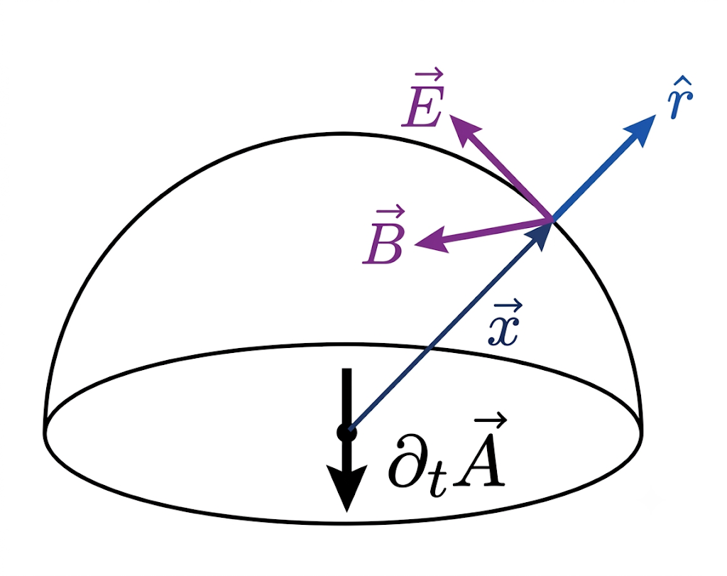
3.1.1 Radiation power definition
Angular radiation power
Total radiation power
Spherical shell integral (useful when calculating ). For ,
3.1.2 Time-varying dipole
Density
Potential
EMF ()
Poynting vector (for directional dipole )
If , after long-time averaging, the result is simple,
Complex form of resonant dipole
For example, consider a charge pair separated by distance , rotating anticlockwise around the origin in the -plane with constant angular frequency so that the positive and negative charges are , thus
3.2 Resonant radiation
3.2.1 Far field approximation
For infinitely far field , one finds
Note: In order to to maintain consistency with the previous sections and avoid confusion, I consistently use to denote the real retarded time and for its leading-order approximation, rather than before but here in the class.
Consequently, for any field function in the radiation zone of the form , where the leading-order term is , its gradient can be expanded as,
By retaining only the dominant term, we arrive at the operator equivalence,
Ponyting vector can be calculated as,
3.2.2 Resonant radiation
For resonant radiation
Vector potential and EMF (by retaining only the dominant term),
where and denote the field amplitudes with the factor omitted.
Aerial radiation
For a thin antenna of length , the current distribution forms a standing wave given by,
Vector potential and EMF (by retaining only the dominant term),
Definition: resistance of antenna ()
for short antenna discussed above with ,
3.2.3 Small source approximation
Approximation Regime: localized, long-wavelength source in the radiation zone with is the wavelength of the radiation. This implies that and we can taylor-expand to obtain,
Electric dipole radiation
Potential and EMF
Radiation
where and denote the amplitudes with the factor omitted.
For example, a directional dipole
Another example, if (electron in uniform circular motion),
Magnetic dipole radiation
Potential and EMF
Radiation
where and denote the amplitudes with the factor omitted.
For example, a directional dipole
Electric quadruple radiation *
Potential and EMF
Radiation
where and denote the amplitudes with the factor omitted.
For example, a planar quadrupole in the -plane with , where the only non-zero components are ,
where . The first term scales as (velocity field ), while the second term scales as (acceleration/radiation field ).
3.3.2 EMF of uniformly moving point charge
where is the angle between present position and the velocity, the former satisfies,
However, this form is seldom used in practical radiation problems as the total radiated power of the field is zero.
3.3.3 Radiation of moving point charge
Radiation field form a right-handed orthogonal triad, thus
Non-Relativistic Limit
For the non-relativistic limit (), and , . This reduces directly to Larmor's formula,
Note: This result is consistent with the instantaneous electric-dipole radiation formula for a single charge. By identifying the dipole moment as (hence ), the total power yields identical results.
Relativistic Case
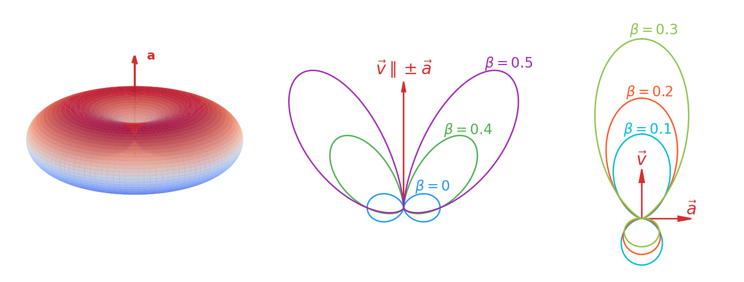
For (), let . The angular radiation distribution becomes,
As (a bit like ), the denominator concentrates the radiation into a sharp forward cone with a characteristic opening angle of .
For (),
where is the azimuthal angle. In the ultrarelativistic limit , this expression describes the synchrotron radiation.
The angular radiation distributions for the three conditions discussed above are illustrated below,
The fully relativistic generalization (Liénard's formula), is given by
In the particle's instantaneous rest frame, the radiation carries away non-zero energy () but zero 3-momentum (). Thus,
Covariantly transfer to the laboratory frame yields,
Lorentz Transformation of *
Let be the laboratory frame and be the instantaneous rest frame of the moving particle. Let denote the angular radiation power emitted per retarded time in , and in . The angular distribution transforms as,
where (or ) is the angle between the velocity and the direction of observation in (or ).
An accelerating charged particle interacts with its own self-field. In the non-relativistic limit, this defines the electromagnetic mass in terms of the electrostatic self-energy of the charge distribution,
The rest energy of electron is for the surface charge shell model, and for the uniformly charged sphere model. Hence, the observed physical mass becomes,
If we assume that the observed mass of electron is entirely electromagnetic (setting ), we could define the classical electron radius after ignoring model-dependent geometric factors of order unity,
To account for the continuous radiation of 4-momentum, a self-force term must be incorporated into the particle's relativistic equation of motion. This yields the Abraham-Lorentz equation,
By demanding the kinematic consistency condition , the covariant radiation reaction force is derived as,
In the instantaneous rest frame of the particle (or, approximately, for non-relativistic particles as seen in the lab frame), where , , and , the radiation reaction force decomposes into the time and spatial components,
The time component gives the irreversible radiated power , reproducing the Larmor formula. The spatial component is precisely the Schott term, which has no time component in this frame and hence does no work. It encodes a reversible energy exchange with the near-zone induction fields, which can return energy to the particle when the acceleration changes.
4 Electromagnetic waves
4.1 EM waves in the medium
4.1.1 Wave equation
The constitutive relations for a homogeneous, isotropic, lossless linear medium, are
Maxwell equations in the absence of free sources (, )
The wave equation
The phase and group velocity are,
We usually consider non‑magnetic media (). One has .
Monochromatic plane‑wave solution
define the intrinsic impedance , so .
The invariant square of the wave vector
In vacuum and , while inside a typical dielectric , the wave vector is spacelike (), corresponding to a subluminal phase speed.
4.1.2 Energy (flow)
Electromagnetic energy and energy flow
The energy transport velocity equals the phase velocity , which means the energy flows with the wave.
Average energy and energy flow
4.2 EM waves on the surface of the medium
Let medium 1 () and medium 2 () be homogeneous, isotropic, lossless linear dielectrics with parameters and . The planar interface is the plane, with unit normal pointing into medium 2. A monochromatic plane wave of angular frequency is incident from medium 1.
4.2.1 Laws of reflection and refraction
Incident, reflected, and transmitted waves
with , , and . The corresponding magnetic fields are ().
Boundary condition
Laws of reflection and refraction
Continuity of the tangential fields at for all requires the phase factors to match,
Assuming the plane of incidence is the -plane. Since , , this gives the law of reflection,
With one obtains Snell's law,
4.2.2 Fresnel equations *
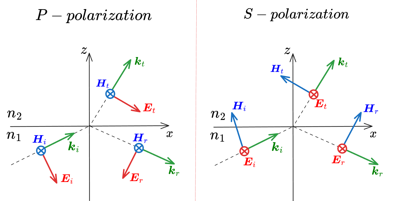
In this section, we follow the reflected convention that reflection reverses the sign of the tangential field parallel to the plane of incidence, while preserving the perpendicular tangential field as the diagram displayed above.
P‑polarization ( parallel to the plane of incidence)
Let . Tangential and (using ) continuity gives,
For simplicity, here define the parameters , . Solving for and gives,
Solving for and gives,
For non‑magnetic media (), , and these reduce to the standard Fresnel formulas.
S‑polarization ( perpendicular to the plane of incidence)
Let . Tangential continuity gives,
which become,
Reflectance and transmittance
The power normal to the interface (time‑averaged) defines
Energy conservation for lossless media ensures . For P or S-polarization,
Brewster angle
For P‑polarization, if (the same as when ) in non‑magnetic media. Together with Snell's law this gives
At this angle the reflected wave is purely S‑polarized.
Assuming (). For ,
The component is reversed (phase diff ) while the component, referred to the reflected convention, appears unflipped. However, the relative phase between the and components changes by . Hence, the handedness (the sense of rotation from toward with thumb along ) is reversed: an incident left‑handed ellipse becomes right‑handed upon reflection, and vice versa.
For , , both components are ‑shifted, their relative phase is unchanged, and the handedness remains the same as the incident wave.
Total internal reflection
If , Snell's law gives . When exceeds the critical angle
and becomes purely imaginary. Then , the transmitted wave becomes evanescent, and total internal reflection occurs.
The constitutive relations for a homogeneous, isotropic, linear conductor,
Also, inside a homogeneous conductor, any initial free charge accumulation decays exponentially to zero on a timescale of ( for copper). We can safely assume .
Maxwell equations (assuming time-dependence)
The wave equation
To look for plane-wave solutions propagating along the -direction, we write in terms of its real and imaginary components,
The plane wave solution propagating along becomes .
4.3.2 Good conductor
The good conductor limit
A medium behaves as a good conductor when the conduction current heavily dominates over the displacement current, i.e.,
Under this approximation, the expressions for and converge to the same value,
The skin depth (The characteristic distance over which the wave's amplitude attenuates by a factor of ) is
Inside a good conductor, the wave field dies out almost entirely within a few skin depths. For high frequencies, is on the order of micrometers, restricting the fields and currents to the very outer edge of the material.
Complex intrinsic impedance
For a good conductor,
Hence, for the plane wave solution propagating along : ,
Which means: Firstly, lags behind by a temporal phase angle of ; Secondly, The magnetic energy density () is vastly larger than the electric energy density () by a factor of , meaning the wave becomes almost purely magnetic.
Good conductors is good reflectors
Consider an electromagnetic wave in a lossless Medium 1 (air with ) is incident upon a good conductor (Medium 2, with finite but large ). The wave vector in Medium 2 becomes complex,
Which means the good conductor reflects nearly all of the incident field back into Medium 1, and the tangential components of the incident and reflected waves vanish at the interface, also leaving no transmitted wave emerging into the conductor: . Thus, is normal to the conductor surface, while is tangential.
Boundary condition for good conductor ( is pointed to conductor (Medium 2))
4.3.3 Resonator
Consider a hollow rectangular cavity with dimensions , , and . The fields inside must satisfy the time-harmonic Helmholtz equation , where .
Applying the separation of variables under the boundary conditions restricts to discrete values,
where at most one of the integers can be zero for a given mode. This yields the discrete resonant frequencies of the resonator,
4.3.4 Waveguide tube
The rectangular waveguide
Consider a hollow waveguide with a rectangular cross-section of width along the -axis and height along the -axis, with . The inner PEC (perfect electric conductor) walls are located at and . We look for harmonic waves propagating down the tube,
which satisfy,
TM Modes (Transverse Magnetic)
For TM waves, the longitudinal magnetic field vanishes (), and we solve for . The boundary conditions are,
Applying the separation of variables yields,
Plunging this back into the Helmholtz equation yields the discrete cutoff wavenumber ,
Crucial Note: If either or , the entire field collapses to zero. Thus, the lowest-order TM mode is the mode.
TE Modes (Transverse Electric)
For TE waves, the longitudinal electric field vanishes (), and we solve for . The boundary condition translates via Maxwell's equations into a Neumann boundary condition for (its normal derivative must vanish at the walls),
This restricts the solutions to,
The cutoff wavenumber shares the exact same algebraic form as the TM modes. However, because cosines do not vanish when their arguments are zero, one of the indices ( or ) can safely be zero. Thus, the lowest-order TE mode is the or mode.
The Dominant Mode:
If , the lowest-order TE mode is the mode,
The transverse-longitudinal bridge *
This formulation serves as a powerful tool for applying boundary conditions, as well as for deriving all remaining field components once a single longitudinal component is determined.
Using,
Expanding these equations into Cartesian components (replacing with ) yields,
By solving the simultaneous pairs (1)-(5) and (2)-(4), we form the algebraic bridge that explicitly expresses the transverse field components in terms of the longitudinal components ,
The general waveguide *
Now we take a hollow tube of any arbitrary cross-section shape into account.
To do this efficiently without solving all 6 components of and simultaneously, we split the del operator and the fields into transverse () and longitudinal () components,
By substituting these split forms back into Maxwell's curl equations ( and ) and separating the components orthogonal to , one obtains,
where .
Thus, once you solve the 2D scalar Helmholtz equation for a given boundary, taking spatial derivatives () instantly yields the entire transverse field structure.
The Impossibility of TEM Modes in Hollow Tubes
A TEM (Transverse Electromagnetic) wave requires both and . Looking at the general decomposition formulas above, if , then and would instantly become zero unless .
If , the transverse electric field reduces to a static-like potential problem: with . For a hollow, single-conductor tube, the entire bounding perimeter forms a single, continuous equipotential surface. By the uniqueness theorem of electrostatics, everywhere inside, meaning .
Thus, TEM waves cannot exist inside a hollow, single-conductor waveguide.
Dispersion characteristics
For any chosen mode with a cutoff wavenumber , the longitudinal propagation constant is,
If , is real. The wave propagates freely, while for , becomes purely imaginary. The fields decay exponentially as .
Because the wave bounces off the walls rather than traveling in a straight line, the phase fronts and the energy transport move along the axis at different speeds:
Phase Velocity
Group Velocity
and
4.4 Lorentz model *
The Lorentz model treats a bound electron in a dielectric as a damped harmonic oscillator driven by the local electric field. We use the same time convention as above, .
4.4.1 Equation of motion for a bound electron
Let be the displacement of an electron relative to the positive nucleus. For a monochromatic field ,
where is the natural frequency of the bound electron and is the damping rate. Therefore,
The induced dipole moment of one atom is,
Thus the atomic polarizability is,
4.4.2 Electric susceptibility and dielectric function
If the number density of oscillators is , then
so that
For several resonance modes,
where is the oscillator strength. The complex permittivity is,
and for a non-magnetic dielectric,
Writing for a single resonance gives,
The real part determines dispersion, while the imaginary part determines absorption.
4.4.3 Dispersion and absorption
Absorption
For weak absorption, write . A plane wave propagating in the direction is then,
so the intensity obeys,
The time-averaged absorbed power density is,
Near , has a peak and the wave is strongly absorbed. Away from resonance, becomes small and the medium is approximately transparent, but still varies with frequency, producing dispersion.
(Anomalous) dispersion
For a weakly absorbing dielectric, , or equivalently . From one obtains,
Therefore, in the weak-absorption limit ,
Only for a dilute or weakly polarizable medium, , can one further expand
The frequency dependence of is called dispersion. The phase velocity and group velocity are,
For the Lorentz oscillator,
Hence, below resonance (), usually and ; above resonance (), and decreases. Near resonance, let and assume , then
and
Therefore, in the resonant absorption band,
so that
This region is called anomalous dispersion. In contrast, away from strong absorption bands, one usually has,
which is called normal dispersion.
Note: Strong anomalous dispersion appears together with strong absorption. Therefore, even if the formal expression for becomes larger than or negative near resonance, it does not represent superluminal information transfer; in this region the pulse is strongly distorted and the simple transparent-medium group-velocity picture breaks down. Causality links absorption and dispersion through the Kramers–Kronig relations - Wikipedia.
4.4.4 Drude model as the free-electron limit
For free electrons in a metal or plasma, the restoring force vanishes, i.e. . Then,
In the collisionless limit ,
Thus, for , and the wave cannot propagate in the bulk; for , and the wave can propagate.